STRONA FORTECO

GOSFLOW N
RĘKAWICE OCHRONNE
Nowa cena netto
PLN
3.62
Cena brutto
PLN
4.45
Cena netto
PLN
3.73
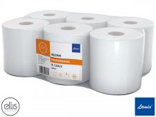
HLA-RECEL-120 W
RĘCZNIK PAPIEROWY
Nowa cena netto
PLN
14.94
Cena brutto
PLN
18.38
Cena netto
PLN
15.39
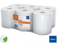
HLA-RECELV-150 W
RĘCZNIK PAPIEROWY
Nowa cena netto
PLN
102.85
Cena brutto
PLN
126.51
Cena netto
PLN
105.94
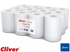
HLA-REMAK-100 W
RĘCZNIK PAPIEROWY
Nowa cena netto
PLN
9.44
Cena brutto
PLN
11.61
Cena netto
PLN
12.01

HLA-REMAK-130 W
RĘCZNIK PAPIEROWY
Nowa cena netto
PLN
10.21
Cena brutto
PLN
12.56
Cena netto
PLN
10.51
HLA-REMAK-65 W
RĘCZNIK PAPIEROWY
Nowa cena netto
PLN
5.60
Cena brutto
PLN
6.89
Cena netto
PLN
5.77
HLA-REMAKV-150 W
RĘCZNIK PAPIEROWY
Nowa cena netto
PLN
95.33
Cena brutto
PLN
117.26
Cena netto
PLN
98.19
HLA-REMAKV-200 Z
RĘCZNIK PAPIEROWY
Nowa cena netto
PLN
56.88
Cena brutto
PLN
69.96
Cena netto
PLN
58.59